How-To's & Guides

Husqvarna Automower® - Robotic lawn mower with boundary wire installation

Maximise your mower's potential by ensuring a correct installation in your garden. Here is our easy to follow, step by step guide and instructional video to help you during a boundary wire installation.

Video guide

An easy video guide on how to install a Husqvarna robotic lawn mower with boundary wires. Click here for boundary wire free installation support.
Video
How to install Husqvarna Automower 11m55s 16:9 Master

Step 1: Download the Automower® Connect app

Download the Automower® Connect app from AppStore or GooglePlay. Once downloaded, sign up and create a Husqvarna account. Log in to your Husqvarna account in the app and select your mower.

Step 2: Pair the mower with the app

Turn your mower on and follow the instructions in the app.
Note: If your mower has low battery then complete this after step 4.

Step 3: Place the charging station

Locate the best place for the charging station. This needs to be placed on a flat level surface with an open area in front of it. Connect the power supply’s low voltage cable to the charging station and the power supply, then connect the power supply to a 100-240 V wall socket. For Automower® Aspire R4 and Automower® 320 NERA models: if you want your robotic lawn mower to download and install new firmware updates automatically, the charging station must be located in an area with Wi-Fi coverage.

Illustration Use Quick Guide image

Step 4: Charge the mower

Plug in the charging station, then place the mower in it and turn on to charge. You will be able to see in the app that the mower is charging.

Quickguide illustration: plug in charging station

Step 5: Lay the boundary and guide wire

Lay the boundary wire along the edges of the lawn so that it forms a loop around the work area. Use the cardboard ruler, which you can find inserted in the top of the mower box, to measure the optimal distance to lay the wire around the edge of your lawn and when creating islands around obstacles, like a tree.

Lay the wire:

  • 10cm (4in) from obstacles that are lower than 1cm (0.4in) e.g. a pathway
  • 30cm (12in) from obstacles that are between 1-3.5cm (0.4-1.4 in) high e.g. a flowerbed
  • 35cm (14in) from obstacles that are higher than 3.5 m (1.4in) e.g. a wall
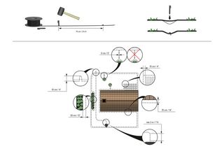
Make a loop with the wire at the point where the guide wire will later be connected, to ensure enough wire to connect it to the guide wire. Attach the wire to the ground with the stakes enclosed in the installation kit.
 
From the charging station lay the guide wire across the lawn to the point on the boundary loop where the connection will be made. Avoid laying the wire at tight angles. See video for further information.
Illustration Use Automower Installation Quick Guide (Next Web)

Step 6: Connect the boundary wire and the guide wire to the charging station

The guide wire leads the robotic lawn mower to remote areas of the lawn and helps the mower to quickly find the charging station. Lay the guide wire under the charging station with at least 1m (3.3ft) straight out in front of the charging station.
 
Note: Automower® Aspire™ R4 must have a guide wire installed and this needs to be attached to the underneath of the charging station base plate using the three clips.
 
Open the connectors and lay the wire ends in the recesses on each connector.
Press the connectors together using a pair of pliers. Then cut off any surplus boundary wire: 1-2cm (0.4-0.8in) above the connectors.
 
Press the connectors onto the contact pins marked L (left) and R (right) in the charging station. It is important that the right-hand wire is connected to the right-hand contact pin, and the left-hand wire to the left-hand pin. Then fasten the connector to the contact pin marked GUIDE on the charging station.
Quickguide illustration: attach wires to charging station

Step 7: Connect the guide wire to the boundary wire
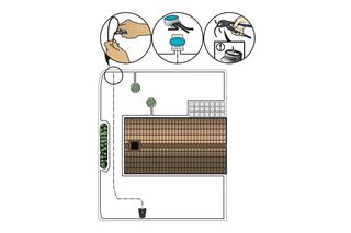
Cut the boundary wire with wire cutters at the centre of the loop that was made in Step 5. Connect the guide wire to the two ends of the cut boundary wire using the accompanying coupler. Press the coupler completely together using a pair of pliers. A green sold light should be showing on the charging station. See the different light status and what they indicate below:
 
Green solid light - Good boundary loop signal.
Green flashing light - ECO mode is activated.
Blue flashing light - Malfunction in the boundary loop.
Red flashing light - Malfunction in the charging station’s antenna.
Red solid light - Fault in the circuit board or incorrect power supply in the charging station. The fault should be rectified by an authorised service technician.
Yellow flashing light - (Automower® Aspire™ R4 only) Malfunction in the guide wire.
Illustration Use Automower Installation Quick Guide (Next Web)

Step 8: Set a schedule in the app and start mowing

Now you are ready to start mowing your lawn. Turn your mower on and enter your pin code. The app will provide additional tips and information to help you optimise your mower, saving you time and helping you achieve the perfect lawn 24/7.
 
For Automower® Aspire™ R4 you can find more information in the Quickguide which can be found under 'Manuals and Documents'.
Automower 305/310 Mark II/315 Mark II with AMC screenshot schedule

Connectivity

There are different ways your mower can connect to the Automower® Connect app. Depending on model you can connect by one or several of the below methods.
  • Bluetooth for connectivity within a 30 metre range of your mower.
  • Wi-Fi for connectivity anywhere while your mower is connected to Wi-Fi.
  • Cellular for connectivity anywhere.
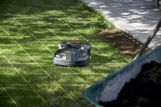
For more information please see the complete operator's manual in the Automower® Connect app or on Husqvarna.com.